
Features:
• Power distribution board with built in OSD
• Onboard 5V regulator output to supply the flight controller
• Onboard 10V* regulator for the video transmitter and FPV camera
• Active on board power filtering
• Flight timer display
• Primary battery on screen voltage display (Volts)
• Two stage low battery on screen alarm alerting you to land
• System current draw on screen display (Amps)
• System battery consumption meter (mAH used)
• Radio reception meter (RSSI) on screen display
• Selectable PAL / NTSC modes
*10V can be used to power cameras labeled as 12V.
Technical specifications:
• 3S- 4S battery compatibility
• 100A max current
• 36mm x 36mm size with standard mount pattern
• 5g weight
Functionality
Auto battery detection
• The board will identify and display whether you are using a 3S or 4S battery and adjust all that it needs to automatically.
Real time flight timer
• Displays actual flight time. If the motors aren’t spinning the timer will pause. This gives you accurate actual in-flight time.
Low battery alarm
• As we know, when you punch the throttle the battery voltage will sag due to the high load without being low on battery. The low battery alarm will actually take your battery’s internal resistance into account and decide whether you’re just drag racing or if the battery is actually low. After the initial “low battery” alarm, if you continue flying and reach critical levels, a secondary warning appears telling you so.
RSSI auto detect
• PWM (FRSKY) or DC RSSI support. 100% auto detect and calibrate. Percentage value output display.
o If you don’t hook up the RSSI pin to your receiver the board will figure this out not display RSSI on the screen.
o If you do use RSSI, the board will auto configure to the receiver type and display the signal strength in percentage value. This assumes you turn on the transmitter first.
Pinout
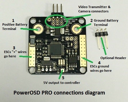
1. Terminal to solder the positive battery connector lead
2. Terminal to solder the ground battery connector lead
3. Solder the positive supply wires from the ESCs here
4. Solder ESC grounds and other grounds to this pad
5. Output of the onboard 5V BEC regulator
Video Transmitter / Camera header pinout

1. RSSI input
2. Video transmitter ground
3. Video transmitter filtered and regulated 10V supply voltage
4. Video Transmitter video signal
5. Camera ground
6. Camera filtered and regulated 10V supply voltage
7. Camera video signal
PAL / NTSC select

NTSC cameras (Default) – Leave the two pads circled open
PAL cameras – Bridge the two circled pads with a solder joint
Appendix
The following table highlights the key differences between the PowerOSD PRO and the previous revisions.

• Power distribution board with built in OSD
• Onboard 5V regulator output to supply the flight controller
• Onboard 10V* regulator for the video transmitter and FPV camera
• Active on board power filtering
• Flight timer display
• Primary battery on screen voltage display (Volts)
• Two stage low battery on screen alarm alerting you to land
• System current draw on screen display (Amps)
• System battery consumption meter (mAH used)
• Radio reception meter (RSSI) on screen display
• Selectable PAL / NTSC modes
*10V can be used to power cameras labeled as 12V.
Technical specifications:
• 3S- 4S battery compatibility
• 100A max current
• 36mm x 36mm size with standard mount pattern
• 5g weight
Functionality
Auto battery detection
• The board will identify and display whether you are using a 3S or 4S battery and adjust all that it needs to automatically.
Real time flight timer
• Displays actual flight time. If the motors aren’t spinning the timer will pause. This gives you accurate actual in-flight time.
Low battery alarm
• As we know, when you punch the throttle the battery voltage will sag due to the high load without being low on battery. The low battery alarm will actually take your battery’s internal resistance into account and decide whether you’re just drag racing or if the battery is actually low. After the initial “low battery” alarm, if you continue flying and reach critical levels, a secondary warning appears telling you so.
RSSI auto detect
• PWM (FRSKY) or DC RSSI support. 100% auto detect and calibrate. Percentage value output display.
o If you don’t hook up the RSSI pin to your receiver the board will figure this out not display RSSI on the screen.
o If you do use RSSI, the board will auto configure to the receiver type and display the signal strength in percentage value. This assumes you turn on the transmitter first.
Pinout
1. Terminal to solder the positive battery connector lead
2. Terminal to solder the ground battery connector lead
3. Solder the positive supply wires from the ESCs here
4. Solder ESC grounds and other grounds to this pad
5. Output of the onboard 5V BEC regulator
Video Transmitter / Camera header pinout
1. RSSI input
2. Video transmitter ground
3. Video transmitter filtered and regulated 10V supply voltage
4. Video Transmitter video signal
5. Camera ground
6. Camera filtered and regulated 10V supply voltage
7. Camera video signal
PAL / NTSC select
NTSC cameras (Default) – Leave the two pads circled open
PAL cameras – Bridge the two circled pads with a solder joint
Appendix
The following table highlights the key differences between the PowerOSD PRO and the previous revisions.